


Service hotline
+86 18518316054
 Current location : Home page > Resources > Papers > Foaming-assisted Electrospinning of Large-pore Mesoporous ZnO Nanofibers with Tailored Structures and Enhanced Photocatalytic Activity
Foaming-assisted Electrospinning of Large-pore Mesoporous ZnO Nanofibers
with Tailored Structures and Enhanced Photocatalytic Activity
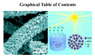
We have demonstrated the growth of large-pore mesoporous ZnO nanofibers with enhanced photocatalytic activity via an improved electrospinning strategy.
1D large-pore mesoporous ZnO materials have attracted tremendous attention because of its outstanding properties and promising applications in a wide range of fields. In the present work, we reported the fabrication of large-pore mesoporous ZnO nanofibers via an improved electrospinning strategy, namely foaming-assisted electrospinning technique, combined with subsequent calcination treatment. The as-fabricated large-pore mesoporous nanofibers were systematically characterized by X-ray diffraction (XRD), scanning electron microscopy (SEM), transmission electron microscopy (TEM) and Brunauer-Emmett-Teller (BET) specific surface area (SBET). The obtained products possess well-designed 1D mesoporous nanostructure with high purity and homogeneous large pore sizes. It is found that the content of foaming agent within the solutions plays a crucial role on the formation of large-pore mesoporous ZnO nanofibers, enabling the growth of the fibers in a controlled manner. The resultant large-pore mesoporous nanofibers exhibit excellent photocatalytic activity and significant stability for hydrogen production compared to conventional solid nanofibers. The present work suggests a facile preparation of the large-pore mesoporous ZnO nanofibers, which may open new doors for them to be potentially applied in photocatalysts.
1. INTRODUCTION
Hydrogen production by photocatalytic water splitting is a promising technology for the alleviation of the limited fossil fuels supply and the environmental contamination.1-4 Following the seminal publication of Fujishima and Honda on illuminated TiO2 splitting electrodes for water splitting four decades ago,5 numerous efforts have been devoted worldwide to design and pursue high-performance photocatalysts with improved photoactivity and stability.6-9 Recently, major attention has been devoted to the preparation of mesostructured photocatalysts owing to their intrinsic structural features.10-13 Compared with the bulk counterparts, mesoporous materials have the ability to interact with atoms, ions, molecules or even nanoparticles not only at the external surfaces, but also throughout the whole internal of the materials.14-17 Particularly, the large-pore mesostructured materials possess more fascinating features such as enlarged pore sizes that could favor the efficient ability of infiltrating the heterogeneous components into the mesoporous channels for achieving much higher loadings, which result in large surface areas, abundant surface states, and enhanced photocatalytic performances.18-23 Of various mesoporous architectures, the one-dimensional (1D) nanostructures hold the robust geometry that could remarkably inhibit the agglomeration of nanoparticles, which contributes to the stable photocatalytic performance.24,25 Hence, semiconductor photocatalysts designed to be 1D large-pore mesostructure is of paramount interest to explore the great potential candidate.
Zinc oxide (ZnO) is one of the most important semiconductors because of their outstanding features such as nontoxicity, direct wide band gap (3.37 eV), large exciton binding energy (60 meV), shortened pathways for electron transport, chemical stability and so on, which make them promising in gas sensors, photocatalysis and drug carriers.
prominent research interest referring to its photocatalytic applications, as they can supply more surface active sites and make charge carriers transport easier, leading to an enhancement of the performance.30-33 Nevertheless, the photocatalytic capability and efficiency are still relatively low because of the inherent low porosity and instability of the traditional mesoporous ZnO materials. Note that the 1D large-pore mesostructures fully embody the substantial advantages, which is considered as the most promising morphology used in the photocatalytic fields. Therefore, it is of a great significance to explore a simple and economical approach to conveniently synthesize 1D large-pore mesoporous ZnO materials with high porosity and satisfactory pore sizes. Here, we report a simple strategy for the synthesis of large-pore mesoporous ZnO nanofibers through a foaming-assisted electrospinning process inspired by our previous work,34 using diisopropyl azodicarboxylate (DIPA) as the foaming agent, wherein the initially released abundant vapors for the creation of pores with uniform spatial distribution in the spun precursor fibers during the subsequent calcination process. The as-fabricated nanofibers exhibit a well-defined 1D nanostructure with homogeneous pores, high purity and large pore sizes of ~35 nm. We also find that the content of DIPA in the precursor solutions play a crucial role on the growth of large-pore mesoporous ZnO nanofibers. The as-fabricated ZnO products were explored in photocatalytic activity for hydrogen photocatalysts for evaluation of their properties. It is believed that the present work will inspire the study of large-pore mesoporous ZnO materials, which could lead to excellent performances as photocatalysts.
2. EXPERIMENTS
2.1. Sample Preparation.
The formation process of the large-pore mesoporous ZnO nanofibers is based on a foaming-assisted electrospinning method. All the reagents were purchased from Aladdin Chemical Reagent Co. Ltd. and were directly used without any purification. In a typical procedure, 1.0 g of polyvinylpyrrolidone (PVP, MW≈1300000) was dissolved in a mixture of ethanol (6 g) and deionized water (6 g) under continuous stirring at room temperature to form a homogeneous viscous solution. Then 2.8 g of zinc acetate (ZnAc, Zn(CH3COO)2·2H2O, 99.99% ) were added to the above solution and the mixture was stirred at 60 °C for 20 min. Subsequently, a varying amount of diisopropyl azodicarboxylate (DIPA, C8H14N2O4, 95%) was added to the pellucid solution. The DIPA compositions were increased from 0 to 7 wt %, which were detailed shown in Table 1. The obtained samples were referred as A, B, C, D and E, respectively. After stirring at 25 °C for 60 min, the white precursor solution of PVP/ZnAc/DIPA composites was obtained. In the electrospinning process, the resultant solution was spun using a metal injection needle with an inner diameter of 0.41 mm at an applied voltage of 15 kV. The as-spun fibers were collected onto the grounded wire mesh (20-mesh), which was placed 18 cm away from the spinneret. Afterward, the polymer fibers were calcined at 500 °C with a heating rate of 3 °C /min for 2 h in air. The final products were naturally cooled down to the ambient temperature.
2.2. Characterization. Scanning electron microscopy (SEM) analysis and energy-dispersive X-ray (EDX) spectrum
were carried out by an S-4800 microscope (Hitachi, Japan) operated at an acceleration voltage of 5 kV.
X-ray powder diffraction (XRD) pattern was recorded on an X-ray diffractometer (D8 Advance, Buker,
Grmany) with Cu Kα radiation (λ=1.5406). The Brunauer-Emmett-Teller (BET) specific surface area
(SBET) of the as-obtained sample was analyzed by nitrogen adsorption in a Micromeritics ASAP 2020 HD88 nitrogen adsorption apparatus (USA). The sample was degassed at 200 °C for 2 h before nitrogen
adsorption measurements. The adsorption isotherm was used to determine the pore size distribution
using the Barret-Joyner-Halender (BJH) method, assuming a cylindrical pore model. Transmission
electron microscopy (TEM) images were collected on a JEM-2010F electron microscope (JEOL, Japan),
using a 200 kV accelerating voltage.
2.3. Photocatalytic Hydrogen Production.
The photocatalytic hydrogen production experiments were performed in an online photocatalytic hydrogen generation system (CEL-SPH2N, Binjing China Education Au-Light Co. Ltd.) at 10 °C and −0.1 Mpa. A 300 W xenon arc lamp (CEL-HXF300, Au-Light, Binjing) was used as light source (14V, 16A, 16 cm far away from the photocatalytic reactor).

In a typical photocatalytic experiment, 100 mg of
catalyst was dispersed with a constant stirring in 50 mL of mixed aqueous solution containing 0.35 M
Na2S (≥98.0%) and 0.25 M Na2SO3 (ACS). Before irradiation, the suspension of the catalyst was
dispersed in an ultrasonic bath for 20 min, and then was vacuumized for 30 min to remove the air inside
and to ensure that the reaction system is under anaerobic conditions. An 8 mL sample of the generated
gas was collected intermittently through the septum, and hydrogen content was analyzed by gas
chromatograph (GC7900, TECHCOMP, China, nitrogen as a carrier gas and 5 Å molecular sieve
column). Once the photocatalytic reaction of a testing cycle in 6 h was complete, the reactor was
degassed in vacuum for 30 min before starting the subsequent cycle.
3. RESULTS AND DISCUSSION
3.1. Phase Structures and and morphology.
The obtained as-spun precursor nanofibers and their corresponding calcined products were firstly observed under SEM. Fig. 1(a) shows a typical SEM image of as-spun polymer precursor of Sample D under a low magnification, revealing that the obtained products are dense fiber-like morphology with diameter in the range of ~500 nm and lengths up to several micrometers. Under the higher magnification observation (Fig. 1(b)), the precursor nanofibers are uniformly sized along the axial direction and have smooth surface texture owing to their amorphous polymeric property. Fig. 1(c−f) display the typical SEM images under different magnification of the corresponding calcinated nanofibers. Notably, the initial long precursor fibers have been completely converted into porous nanofibers with a high purity (Fig. 1(c)). However, as compared to the straight precursor nanofibers, the obtained porous products are shaped with curled morphology and the fiber diameter is increased to ~570 nm (Fig. 1(d)). These variations are mainly due to the decomposition of the foaming agent, which produced huge amounts of gas during the annealing process, leading to the fiber swelling and distortion. Closer observation of the fiber bodies under higher magnification (Fig. 1(e)) suggests that numerous pores with irregular shapes are randomly distributed within the nanofibers and the average pore size is roughly in a mean width of ~35 nm, indicating that large-pore mesostructured 1D products were obtained via the present foaming-assisted electrospinning method. Fig. 1(f) depicts a representative cross-section of the large-pore mesoporous nanofibers, confirming that the 3D interconnected pores exist throughout the fiber body .
The element composition and crystal structure of the result product were studied by EDS and X-ray diffraction (XRD). Fig. 2 (a) illustrates the typical EDS spectrum of Sample D, confirming the presence of Zn and O in the mesoporous nanofibers. The atomic ratio of Zn to O is close to 1:1, implying the mesoporous nanofibers are ZnO with a high purity. The detected C signal arises from the conducting resin to support the SEM sample. Fig. 2 (b) presents the XRD pattern of the as-prepared large-pore mesoporous nanofibers. All of the diffraction peaks can be well indexed to the wurtzite phase of ZnO (JCPDS: 36-1451) and no characteristic peaks of other impurities were observed, which further illustrate a high purity of the prepared products. The average crystallite size of ZnO was calculated ~33.8 nm from the three different prominent planes of (100), (002), and (101) by using Scherrer formula. It is worthy to note the sharp diffraction peaks which suggest a good crystallinity of the large-pore mesoporous nanofibers under current experimental conditions.
Further characterization of the large-pore mesoporous nanofibers was carried out by TEM. Fig. 3(a-b) show the typical TEM images of the randomly selected fiber under different magnifications. In good agreement with the SEM observations, the homogeneous mesoporous structure is clearly observed. It is worthy to mention that such a long mesoporous nanofiber survived the scratching and ultrasonic treatments during the TEM sample preparation process, indicating their high structural robustness. Fig. 3(c) is the corresponding selected area electron diffraction (SAED) pattern (Fig. 3(c)) recorded form the marked area of A in Fig. 3(a). The diffraction spot rings indicate its polycrystalline nature and could be sequentially indexed to the crystal planes of a wurtzite phase of ZnO (JCPDS: 36-1451). Furthermore, a representative high magnification TEM (HR-TEM) image (Fig. 3(d)) recorded from the marked portion B in Fig. 3(b), implying that the large-pore mesoporous nanofibers possess a well-defined crystal structure with few defects such as dislocations and stacking faults. Fig. 3(e) is an enlarged lattice fringe image of the marked area of C in (d) and the measured d-space of 0.282 nm between two sets of fringes responds to the (100) plane of the hexagonal wurtzite structure ZnO, as already indicated by the XRD analyze.
To achieve the fabrication of large-pore mesoporous ZnO nanofibers in a controlled manner, another four experiments are carried out by adjusting the DIPA content in the initial solutions (see Table 1). Fig. 4 display the representative SEM images under different magnifications of the result products of Samples A, B, C and E. The results suggest that, when the DIPA was absent from the solutions (Fig. 4(a1-a2)), only ordinary solid fibers without pores could be obtained, suggesting that the introduced foaming agents are critical for the formation the mesoporous structures. However, once the DIPA content is increased to 7 wt % (Fig. 4(e1-e2)), the obtained products are mesoporous microspheres instead of fiber shapes. It may be attributed to the too many vapors released from the introduced DIPA foaming agents, which creates plethoric pores and segments the fibers with nano/microsized units, forming the mesoporous microspheres in the end. Thus, the exorbitant content of DIPA used in the solutions is also not suitable for the growth of the large-pore ZnO mesoporous nanofibers. Moreover, it should be noted that the low content level of DIPA (such as 4 wt %) is insufficient for the growth of well-defined mesoporous fibers and there is merely some sporadic pore distribution in the fiber bodies (Fig. 4(b1-b2)). According to the present experimental results, when the DIPA content is 5 wt % and 6 wt %, the well-defined large-pore mesoporous ZnO nanofibers can be obtained via the foaming-assisted electrospinning method (Fig. 4(c1-c2) and Fig. 1(c-f)). As a consequence, it may be guaranteed for the growth of large-pore mesoporous ZnO nanofibers when the DIPA content in the solutions was designed in the range of 5−6 wt %.
3.2. Tentative Mechanism of samples formation. The formation mechanism of the large-pore mesoporous structure is attributed to the special chemical properties of the foamer, which could produce abundant gas during its decomposition. To account for this, a proposed schematic diagram is illustrated in Fig. 5. Firstly, the DIPA was added into the initial solutions and uniformly assembled into the precursor fibers by means of electrospinning. During the calcination process, once the heating temperature reach the value for DIPA decomposition (~120 °C), it would continually release abundant vapor phases (e.g. CO2, NO2 and H2O), leaving behind highly uniform mesopores distributed in the precursor fibers. This is confirmed by the observation of the fibers after air calcination at 300 °C (Fig. S1, ESI†). Then, with increasing of the temperature, PVP would completely decompose into vapor phase and be brought out of the furnace. As while, ZnAc would be converted into inorganic ZnO to construct the large-pore mesoporous fiber matrix.
3.3. BET Surface Areas and Pore Size Distributions.
The effect of DIPA on the BET surface area and pore structure of the prepared samples was investigated by using Nitrogen adsorption measurements. Fig. 6 shows the typical nitrogen adsorption-desorption isotherms and the corresponding pore size distribution curves of Samples A, B, C, D and E. All the nitrogen adsorption-desorption isotherms exhibit type IV curves with H3 hysteresis,35 implying the presence of mesopores. As shown in Table S1 (ESI†), the BET surface area (SBET) of Samples A, B, C and D increases with increasing the DIPA content, from 8.23 to 12.6 m2 /g, indicating that the foaming agents can create the pores throughout the entire body of fibers and significantly enhance the SBET of the resultant nanofibers. The results are further confirmed by the corresponding pore size distribution. As shown in the inset of Fig. 6, Sample A has macropores with a peak pore diameter of around 100 nm. When DIPA is introduced, mesopores begin to appear in samples, and the amount of macropores decreases. It should be noted that the peak pore diameter of samples gradually decreases with the increasing DIPA content, and Sample D has the minimum peak pore diameter with an average pore size of 35 nm. While, for Sample E, the too much introduced foaming agent destroyed the fibers structure and made them grow into micro-sized spheres, resulting in the decrease of the SBET.
3.4. Photocatalytic Activities.
The as-prepared fiveZnO products were used as the photocatalysts for evaluation of their
photocatalytic H2-production activities under xenon arc lamp irradiation by using Na2S and Na2SO3
mixture as sacrificial reagents. Fig. 7(a) plots the amounts of hydrogen evoluted from the aqueous
suspensions of the five photocatalysts under growing irradiation time, which was calculated by standard
curves of hydrogen prduction. It can be seen that the H2 yield over the fiver photocatalysts was
continually increased with irradiation time going on, suggesting the sustainability of the prepared
products. After 6 h irradiation, the hydrogen evolutions of Sample A to E is ca. 3863, 4170, 4494, 4748,
3704 µmol g-1, and the dependence of the different products on the corresponding average hydrogen
production is depicted in Fig. 7(b). The imporous ZnO fiber photocatalyst of Sample A and the
microsphere morphology of Sample E show a low photocatalytic activity because of their lower BET
surface area. Interestingly, the introduction of the large-pore mesoporous architecture to the fiber
resulted in a beneficial improvement in the photocatalytic H2 production activity of ZnO. More
interestingly, the hydrogen evolution rate of present lager pore mesoporous ZnO nanofibers is higher
than those of the most reported works for other nano-sized ZnO nanomaterials (see Table S2, ESI†).
Furthermore, the large-pore mesoporous ZnO fiber photocatalyst of Sample D exhibit the highest
hydrogen production rate compared the two others, confirming the relationship between the BET surface
area and the photocatalytic activity. To further investigate their reusability and stability, Sample D is
chosen as the example photocatalyst and reused for photocatalytic H2 production under the same
conditions. As shown in Fig. 7(c), there is nearly no loss of H2 evolution rate after three recycles (18h), indicating its steady photocatalytic performance during photocatalytic reaction. The results suggest that
the as-fabricated large-pore mesoporous ZnO fibers could be served as a potential photocatalyst
candidate for energy conversion to achieve highly efficient and stable H2 evolution. To account for this,
a tentative schematic illustration is illustrated in Fig. 7(d). Firstly, the one-dimensional (1D) nanofibers
could remarkably inhibit the agglomeration of nanoparticles, which contributes to a more stable
photocatalytic performance.36,37 What’s more, the columnar large-pore mesoporous architecture
possesses the interconnected channels, which offers more active sites to adsorb reactants (e.g. water,
Na2S, Na2SO3 groups) and allow the effective transportation of products (e.g. H2).38 That is to say, the
1D large-pore mesoporous nanofibers benefit to the participation materials moving easily into/out of the
framework to yield a higher reaction rate. These combined effects as mentioned above might be
responsible for the enhanced photocatalytic activities of the large-pore mesoporous nanofibers with a
higher activity and stability as compared to the solid counterparts.
4. CONCLUSIONS
In conclusion, large-pore mesoporous ZnO nanofibers were synthesized via foaming-assisted electrospinning strategy combining with subsequent air calcination treatment. The obtained ZnO mesoporous nanofibers possess a thoroughly mesostructure with a high purity and a large pore size of ~35 nm. The employment foamer (DIPA) in the initial solutions plays a determined role on the growth of the large-pore mesoporous ZnO nanofibers, enabling the fabrication of the nanofibers in a controlled manner. The photocatalytic activity for hydrogen evolution under splitting water of the as-fabricated products disclosed that the large-pore mesoporous nanofibers exhibit the highest photocatalytic activity of 791 µmol h−1 g−1, which is higher than that of the conventional solid nanofibers. The methodology and results described in present work may offer a straightforward guide to the immobilization of high performance ZnO mesoporous material, which would pave the way to be possibly utilized in photocatalytic hydrogen production.
Beijing China Education Au-light Co., Ltd.
Room 401, Fengtai Science and technology innovation center, No. 7 Kexing Road, Fengtai District, Beijing
+86 18518316054
eric@aulight.com;info@aulight.com

Scan and pay attention to us